Motorized Faders and the Arduino
As an audio engineer, one fun thing to do is to switch between layers on a digital console as people walk by. Moving faders are a relatively simple concept, but they seem to amaze people. I have to admit, they are pretty cool. But more important than the coolness factor is the amount of flexibility they provide for mixing.
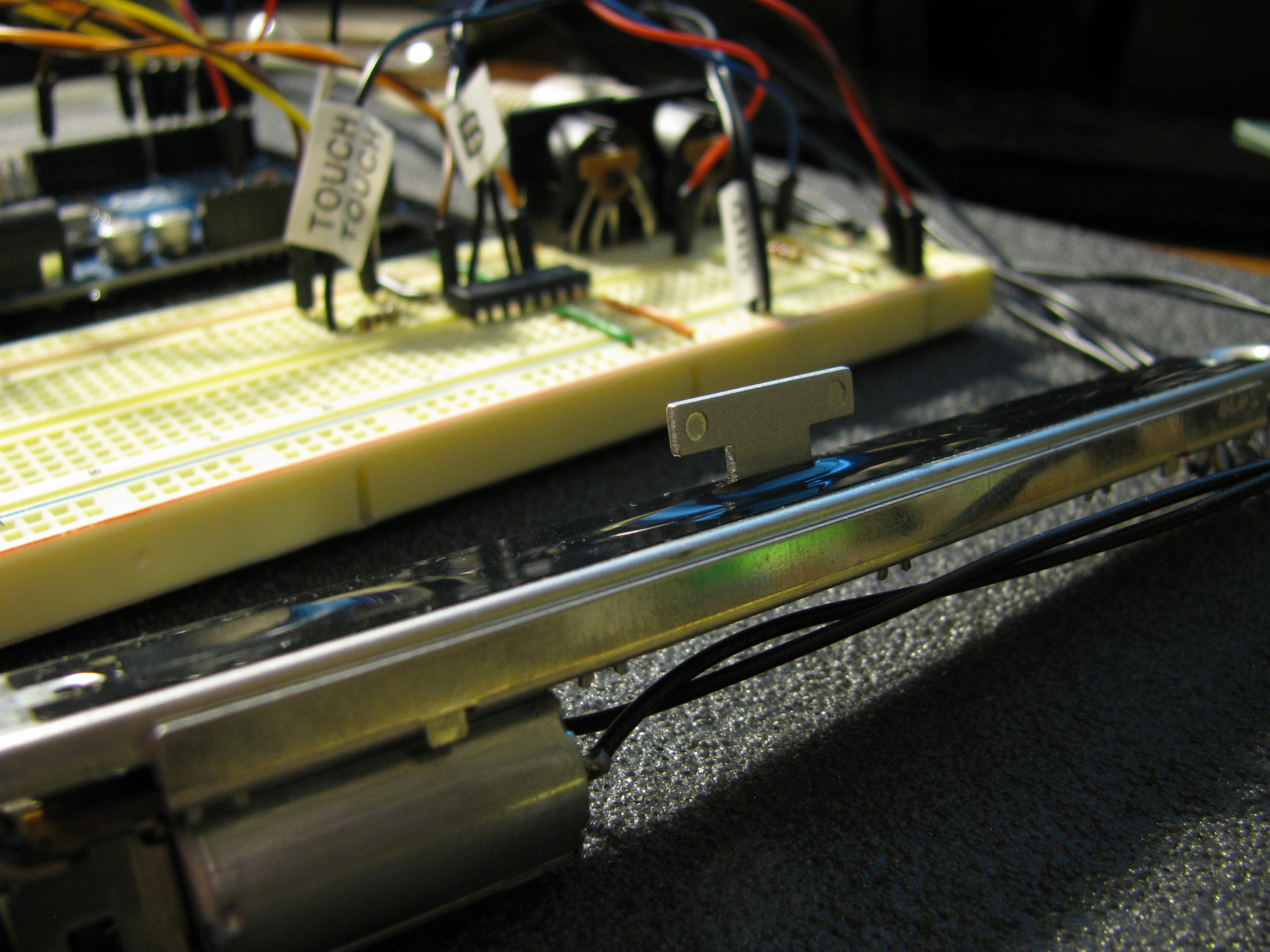
To begin my journey into the world of audio-related programming and hardware development, I decided to do a project to help me understand the technology behind moving fader control. The first part of this project is to make a motorized fader function with the Arduino platform. I’m going to give you step by step instructions to build this part of the project, including the parts I used.
Parts Needed:
- Arduino Uno
- Motorized Fader
- Breadboard
- H-Bridge
- External 9-10 V DC Power Supply
- 1 M Resistor
- 10 k Resistor
- 10 µF Capacitor
- Potentiometer
Motor Control:
The first step in understanding how to control the fader is understanding how to control the motor on the fader. The fader contains a DC motor with two terminals. If power is applied in one direction, the motor goes one way, and if you reverse the power, the motor will go the other way. Using a a digital out pin on the Arduino will give us control of the motor in one direction, but there is no way reverse the direction of the motor without help.
The device that will allow us to control the direction that power is applied to the motor is called an H-Bridge. An H-Bridge is a network of 4-6 transistors that has 2 control pins, 2 output pins, a chip power pin, a motor power pin, and ground. Based on the values of the control pins, the motor will either go forwards, backwards, or it will stop.
| EN | 1A | 2A | FUNCTION |
| H | L | H | Right |
| H | H | L | Left |
| H | L | L | Stop |
| H | H | H | Stop |
The logic table to your right shows exactly which control values are needed to use the H-Bridge to control the motor. As shown in the table, if the control pins are different, the motor will turn, and if they are the same, then the motor will stop. I would recommend wiring the enable pin to +5 V so you don’t have to waste an Arduino pin.
Touch Sensitivity:
The next important thing to deal with is touch sensitivity. Motorized faders generally use a capacitance sensing circuit to determine if someone is touching the fader. Luckily, there is an Arduino library called CapSense that makes this very easy. Using a 1 M resistor and 2 digital pins on the Arduino, you can easily detect when the fader is touched. The following code shows a simple example that will light up the LED on the Arduino when the fader is touched:
#include "CapSense.h"

// Setup your pins and set pin 13 for output
CapSense touchLine = CapSense(touchSendPin, touchReceivePin);

void loop() {
    if (touchLine.capSense(30) > 700) {
        digitalWrite(13, HIGH);
    } else {
        digitalWrite(13, LOW);
    }
}
Being able to detect touch is important for two reasons. The most important one is to protect your motor. Pulling on the fader while the motor is trying to move it can strain the motor, so by using touch sensitivity, you can tell the motor to stop while the fader is being touched. Another reason is for MIDI control. If you are using the fader to write automation, it’s important to inform the DAW that you are touching the fader, so it will know when to start or stop writing automation.
Reading Fader Position:
The easiest part of this project is reading the position of the fader. It works exactly like a potentiometer (because a fader is a potentiometer, just in a different layout). To read the position, connect the bottom of the fader to ground, the top of the fader to +5 V from the Arduino, and connect the wiper to an Analog In pin. From there, you can use analogRead to get the fader’s position (a 10 bit value between 0 and 1023).
Summary:
This project was a fun way to experiment with controlling a fader with the Arduino. There are many improvements that could be made to this project such as adding a full calibration curve for the fader or using PWM (pulse width modulation) to make the fader move slower and more accurately for small movements. The next post will use this project and add MIDI control.
If you have any questions, feel free to comment and I’ll answer them as soon as possible!